RF Microwave PCBs: High-Frequency
Ready for Advanced Applications
Product Benefits

Speed and Adapted Impedance
The low-loss tangent allows high-frequency signals to travel fast through the PCB with controlled impedance. RF and MV designs must avoid return signal seeking the route with the least inductance.

Cost-Effective
Hybrid or Mixed dielectric stack-ups combining FR4 with Low loss & Low dielectric constant materials are often used for RF and MV boards to lower the cost.

High Stability
PCB structure is extremely stable in high-temperature environments. If used in analog applications, these PCBs can operate at 40 GHz.

Components
With mixed dielectric stack-ups and with the use of Blind and Buried via structures it is possible to integrate RF/MV with analog and digital signals and components.
What is RF Microwave PCB?
Definition
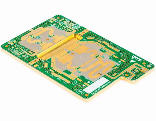
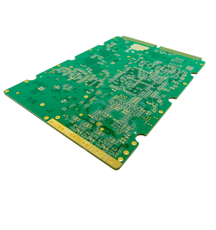
Specifications
Base Material: The base materials used in an RF Microwave PCB are High Performance FR4s, Ceramic Filled Hydrocarbons and PTFEs with woven glass fiber.
Thickness: 0,4 to 2,4mm
Copper Weight: ½oz to 2oz, advanced 3oz.
Lines and Spaces: min. 75um – (Often with specific low etching tolerances)
Layer Count: 1-22 Layers
Surface Finish: OSP, Im Tin, Im silver, ENIG, ENEPIG and Hard or Soft Gold.
Solder Mask: Can be with or without solder mask.
Spectrum
Do you need RF Microwave PCB?
An RF (Radio Frequency) Microwave PCB (Printed Circuit Board) is a type of PCB designed to handle high-frequency signals in the RF and microwave frequency range, typically between 1 MHz and 100 GHz. These PCBs are used in a wide range of electronic applications such as wireless communication systems, satellite communication systems, radar systems, and other high-frequency electronic systems.
Technical Data
RF / Microwave
| RF / Microwave Feature | ICAPE Group RF / Microwave technical specification |
|---|---|
| Layer count | Up to 18 layers. |
| Technology highlights | High definition at track and copper layout with tight impedance control. Edge plating and cavity plating and constellation option. |
| Materials | Low loss and low Dk modified FR4, PTFE, Hydrocarbon. Mixt raw material stack-up option. |
| Base Copper Thickness | From 1/3 Oz base to 3 Oz |
| Minimum track & spacing | 0.060mm / 0.060mm |
| Surface finishes available | OSP, ENIG, ENEPIG, Soft-Gold, Gold fingers, Immersion Tin, Immersion Silver. |
| Minimum mechanical drill | 0.125mm |
| PCB thickness | 0.40mm – 3,2mm |
| Maxmimum dimensions | 425x590mm. |
Learn more about RF Microwave

Webinars on Demand
If you’ve missed a webinar, we now offer various webinars on demand, available upon request!

Industries
Discover how RF Microwave PCB impacts several different industries and multiple fields.
Technologies
Learn about the different technologies in the PCB industry and find which one suits your needs best.
Any questions?
There is an ICAPE Group team close to you and your business. All around the world, our business units are staffed with native experts available to answer all your questions.
Contact us today!
