Flexible PCB Solutions: The Perfect
Fit for Complex Applications
Product Benefits

Cost Saving
The overall cost of the product can be reduced with flexible solutions by reducing assembly time and by replacing cables and connections.

Fast Assembly
Flex PCB eliminates the need for color code wrap bundles of wire and is much faster to install.

High Durability
Flex PCBs are durable and resistant to shock and vibrations making them suitable for both high-reliability devices and handheld products of everyday use.

Space and Weight Reduction
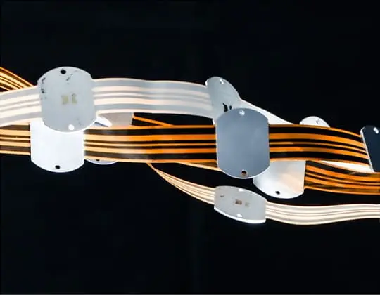
Cables, connectors, and in some instances rigid PCBs can be replaced by Flex PCBs creating lightweight and very dense interconnection in a reduced space.
What is Flexible PCB?
Definition
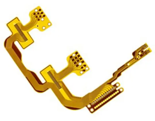
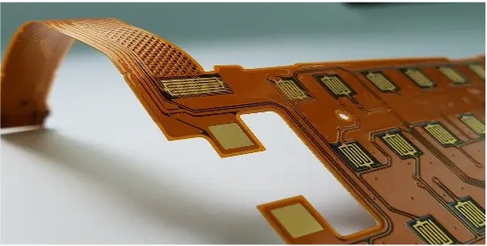
A semi-flex PCB is characterized by its ability to bend or flex to a certain degree while maintaining its structural integrity. This type of PCB is often used to save space in the final product and avoid the use of connectors between two circuit boards. Semi-flex PCBs are manufactured using a combination of traditional PCB fabrication processes such as photolithography, etching, and drilling, as well as specialized techniques for handling the flexible substrate. The final product is a PCB that can bend or flex to a certain degree while maintaining its electrical performance and durability.
Specifications
Base Material: The most common base material used to build a Flexible PCB is Polyimide (PI). It can be used with PTH and is available for the soldering process. PET and PEN can be used for Flexible PCB without soldering needs.
Lines and Spaces: The trace and spacing widths on a Flexible PCB are usually smaller than traditional PCBs to accommodate the limited space and maintain flexibility. A flexible PCB can also be an HDI PCB.
Layer Count: Flexible PCBs can have single-sided, double-sided, and up to 4 layers with a thickness from 25µm to 150µm.
Surface Finish: The surface finish used in Flexible PCBs is usually electroless nickel immersion gold (ENIG)
Do you need Flexible PCB?
Flexible PCBs are used in almost every industry that needs space and weight reductions such as automotive, wearable devices, medical, military, instrumentation, avionics, sensors, or industrial controls.
Features
Copper Properties
| Copper Properties | 1/4 oz (9 µm) | 1/2 oz (18 µm) | 1 oz (35 µm) | 2 oz (70 µm) | 1/2 oz (18 µm) | 1 oz (35 µm) | 2 oz (70 µm) |
|---|---|---|---|---|---|---|---|
| Tensile Strength (KPSI) | 15 | 33 | 40 | 40 | 20 | 22 | 28 |
| Elongation (%) | 2 | 2 | 3 | 3 | 8 | 13 | 27 |
| Vol Resistivity (MOHM CM) | 1,66 | 1,62 | 1,62 | 1,78 | 1,74 | 1,74 |
| 1/4 oz (9 µm) | |
|---|---|
| Tensile Strength (KPSI) | 15 |
| Elongation (%) | 2 |
| Vol Resistivity (MOHM CM) |
| 1/2 oz (18 µm) | |
|---|---|
| Tensile Strength (KPSI) | 33 |
| Elongation (%) | 2 |
| Vol Resistivity (MOHM CM) | 1,66 |
| 1 oz (35 µm) | |
|---|---|
| Tensile Strength (KPSI) | 40 |
| Elongation (%) | 3 |
| Vol Resistivity (MOHM CM) | 1,62 |
| 2 oz (70 µm) | |
|---|---|
| Tensile Strength (KPSI) | 40 |
| Elongation (%) | 3 |
| Vol Resistivity (MOHM CM) | 1,62 |
| 1/2 oz (18 µm) | |
|---|---|
| Tensile Strength (KPSI) | 20 |
| Elongation (%) | 8 |
| Vol Resistivity (MOHM CM) | 1,78 |
| 1 oz (35 µm) | |
|---|---|
| Tensile Strength (KPSI) | 22 |
| Elongation (%) | 13 |
| Vol Resistivity (MOHM CM) | 1,74 |
PI Foil Thickness
| PI Foil Thickness | Thickness Range | Cost | Lead Times |
|---|---|---|---|
| Usual PI Thickness | 25 µm / 50 µm | Standard | Standard |
| Intermediate PI Thickness | 12 µm / 72 µm / 100 µm | + | + |
| Unusual PI Thickness | 9 µm / 125 µm 150 µm | 2 to 3 times the cost of usual thickness | 2 to 4 months |
| Thickness Range | |
|---|---|
| Usual PI Thickness | 25 µm / 50 µm |
| Intermediate PI Thickness | 12 µm / 72 µm / 100 µm |
| Unusual PI Thickness | 9 µm / 125 µm 150 µm |
| Cost | |
|---|---|
| Usual PI Thickness | Standard |
| Intermediate PI Thickness | + |
| Unusual PI Thickness | 2 to 3 times the cost of usual thickness |
| Lead Times | |
|---|---|
| Usual PI Thickness | Standard |
| Intermediate PI Thickness | + |
| Unusual PI Thickness | 2 to 4 months |
Technical Data
Flexible PCB Feature
| Flexible PCB Feature | ICAPE Group Flexible PCB technical specification |
|---|---|
| Layer count | Up to 6 layers, |
| Technology highlights | Reliable and cost effective solution for 3D interconnexion with HDI stack-up to 2 step (N+2) option. Dynamic application with multiple bendings. |
| Materials | PEN and PET raw material (only for SS). Polyimide raw material (SS to ML6). Adhesive or adhesiveless with ED or RA copper. Stiffener (FR4 / PI / Al) |
| Base Copper Thickness | From 1/2 Oz base to 2 Oz |
| Minimum track & spacing | 0.075mm / 0.075mm, Advanced 0,060mm / 0,065mm |
| Surface finishes available | OSP, ENIG, ENEPIG |
| Minimum mechanical drill | 0.15mm |
| Minimal thickness | 0,2mm |
| Maxmimum dimensions | 425x590mm. |
Close to you, you best contact
Learn more about Flexible PCB

Webinars on Demand
If you missed a webinar, we now offer a variety of on-demand webinars, available upon request!

Industries
Discover how Flex PCB impacts several different industries and multiple fields.
Technologies
Learn about the different technologies in the PCB industry and find which one suits your needs best.
Any questions?
There is an ICAPE Group team close to you and your business. All around the world, our business units are staffed with native experts available to answer all your questions.
Contact us today!

